An Index Plate for the Taig Lathe
1. Introduction
An indexing plate by itself seems to have limited use on a lathe. It's fine for anything that can be done with a toolpost mounted cutter like scribing divisions on a dial. But for drilling or milling, you need a rotating tool and, therefore, something like a milling spindle mounted on the cross-slide. For light work perhaps a Dremel or flexible shaft would do.
But the Taig design makes that uneccessary. If you think of a second
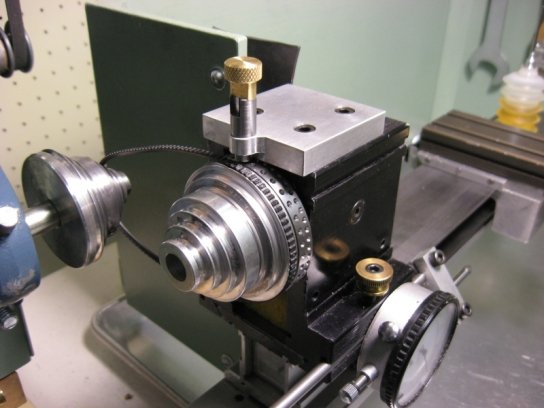
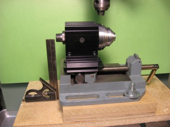
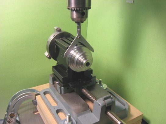
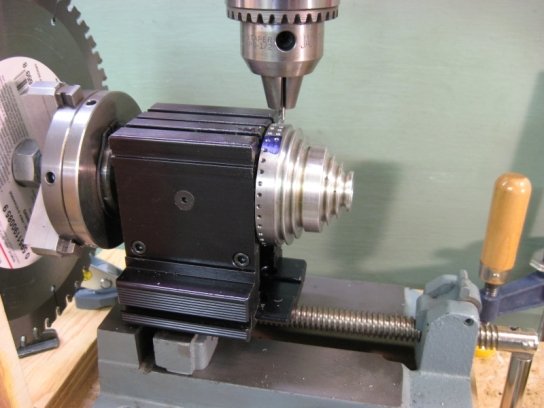
headstock mounted on the mill table as a kind of poor man's rotary table, you can see that the index plate can now be very useful. Fortunately, Taig makes the mounting easy too. Fig 1.1 shows their milling machine Headstock Mounting Plate, Part 200-48, which is readily available as a spare part. Fig 1.2 shows how natural it is to use this for the mill setup. It's not hard to come up with other mounting techniques as you will see in the following use of the drill press.
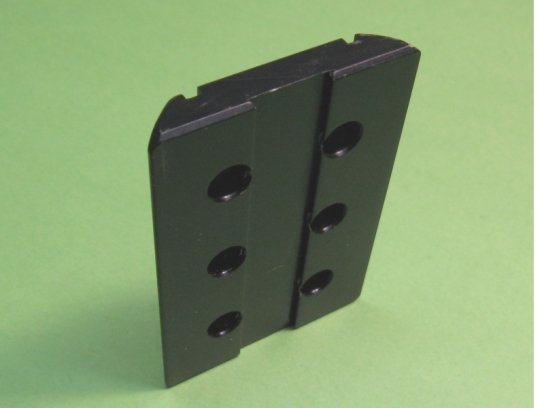 Fig 1.1: Taig Headstock Mounting Plate
 Fig 1.2:
Headstock Mountings on the Mill
Fig 1.2:
Headstock Mountings on the Mill
2. Design
The indexing values I wanted were relatively few, - 2,3,4 and 6 for general use; 25 and 50 for dials suited to leadscrews with 20 or 40 TPI. But even this minimum needed at least two rows of holes and a detent movable from one row to another. In addition, I already had a couple of attachments which overhung the pulley so that ruled out any plate which would extend above the top of the headstock.
From these considerations, I decided on two rows of 50 and 36 holes respectively drilled radially into a 5/16" thick, 2 1/4" diameter plate. This allows index values of 2,3,4,5,6,9,10,12,18,25,36 and 50, more than
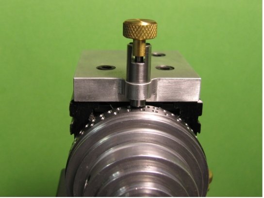
 Fig 2.1:
Pulley and Index Plate Assembly
Fig 2.1:
Pulley and Index Plate Assembly
enough for my needs. The detent is normally locked out of engagement during regular lathe use but can be removed completely to make way for other attachments.
 Fig 2.2:
Index Plate Detent Assembly
Fig 2.2:
Index Plate Detent Assembly
3. Construction
3.1 Pulley Modifications
3.1.1 Making the Index Plate
The index plate is made first so it can later be used as a gauge when machining the pulley. Start with a 3/8" length of 2 3/8" diameter 12L14. This should be long enough to get a finished length of 5/16" even if the initial
faces are not quite square. I had my blank cut off for me by the local metal supplier so it was already reasonably good.
 Fig
3.1.1.1: Index Plate Blank
Fig
3.1.1.1: Index Plate Blank
Mount the blank in the four-jaw chuck, face one side, turn it around, and indicate it true ready for thicknessing and boring.
 Fig
3.1.1.2: Index Plate Reduced to 5/16"
Fig
3.1.1.2: Index Plate Reduced to 5/16"
Reduce the index plate blank thickness to 5/16". Any more than this and there could be insufficient room for proper mounting of the pulley on the headstock spindle.
 Fig
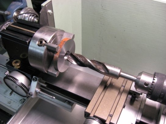
3.1.1.3: Index Plate Drilled for Boring
Fig
3.1.1.3: Index Plate Drilled for Boring
Drill out the index plate with the largest drill you can manage in preparation for boring to final size.
 Fig
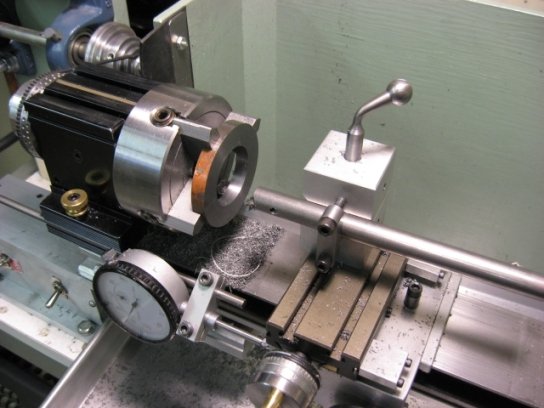
3.1.1.4: Index Plate Bored to 1 3/8"
Fig
3.1.1.4: Index Plate Bored to 1 3/8"
Bore out the index plate to a finished diameter of 1 3/8". Set the index plate aside while the pulley is machined.
3.1.2 Machining the Pulley
To machine the pulley it must be chucked as the working piece so a second pulley is necessary to drive the spindle. If you have a mill you can borrow
the pulley from it. Otherwise you will probably have to buy one.
 Fig
3.1.2.1: The Pulley Mandrel
Fig
3.1.2.1: The Pulley Mandrel
Because of the reduced bore through the smallest sheave, a special mandrel must be turned to hold the pulley for machining. The chucking part is 3/8" diameter. The mandrel part is 5/8" diameter and should be a fairly snug fit for a wobble-free rotation of the pulley.
 Fig 3.1.2.2: Pulley Mounted on the Mandrel
Slip the pulley onto the mandrel, tighten its set screw and grip the mandrel shaft in the three-jaw chuck. Make sure it spins truly and without wobble.
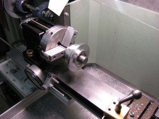 Fig 3.1.2.3:
Boss Turned on the Pulley
Fig 3.1.2.3:
Boss Turned on the Pulley
The index plate is located radially by fitting the hole previously bored in it to a boss turned on the pulley. Turn the boss down axially to within 1/64" or less of the shoulder on the largest sheave.
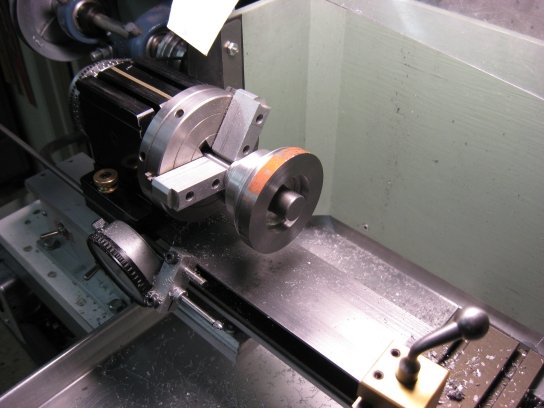 Fig 3.1.2.4: Gauging the Pulley Boss
Use the hole in the index plate as a gauge to get a snug fit on the pulley boss.
3.1.3 Attaching the Index Plate
The index plate is attached to the pulley with 4-40 socket head cap screws. Almost any pattern would do but three screws is kind of elegant and really easy to do with a simple setup on the drill press.The Taig spindle nut is a natural index plate just needing a rotation stop and a spindle lock to produce 2,3,or 6 divisions. The following Figures show how the spindle
wrench provides the rotation, a flat corner brace the stop and a cobbled up small gear clamp the lock. Admittedly, this is not suitable for high precision because the Taig wrench is a pretty sloppy fit on the spindle nut and perfectly repeatable stops are problematic at best. But, with care, it works well enough for this project.
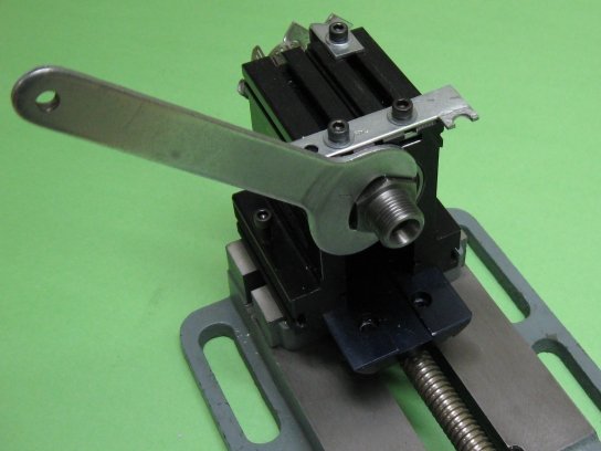 Fig 3.1.3.1: Hex Nut Spindle Index
 Fig 3.1.3.2: Gear Clamp Spindle Lock
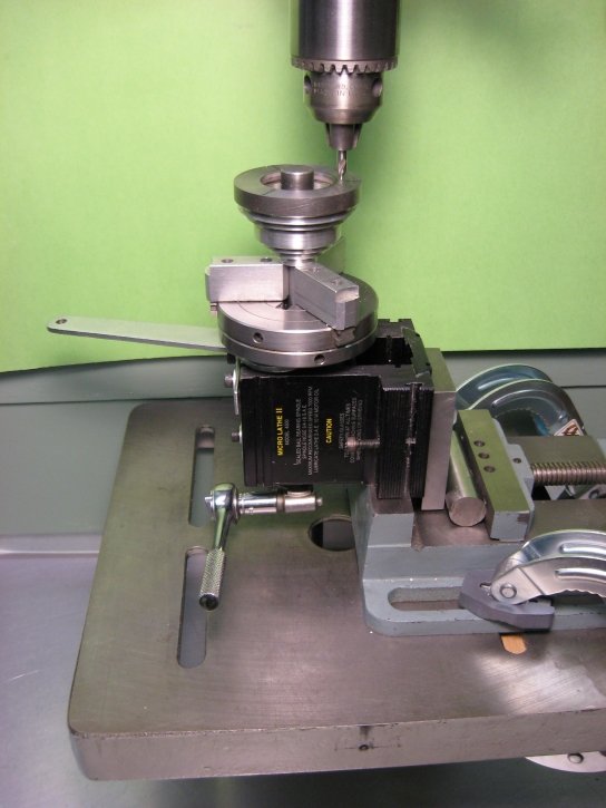 Fig 3.1.3.3: Setting up to Drill the Screw
Holes
Fig 3.1.3.3: Setting up to Drill the Screw
Holes
At left this improvised indexing technique is shown set up vertically on the drill-press table. This simplifies placement of the attachment screws at 120 degree intervals.
Use a little medium strength Loctite to hold the index plate in place while drilling the mounting holes. Clamp the setup on the drill press table so as to drill the plate at a diameter of 1 5/8". This is 1/8" outside the radius of the 1 3/8" diameter locating hole.
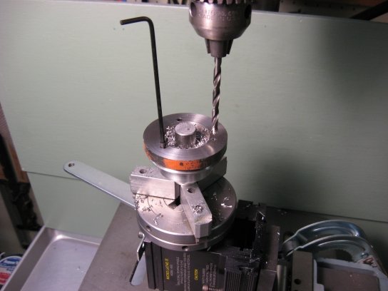 Fig 3.1.3.4: Adding the Screws
The pilot holes are drilled 1/2" deep to take 3/8" long 4-40 socket head cap screws. The plate is 5/16" thick so, after a 1/8" deep counter bore, the thread depth is about 3/16". For blind holes in aluminum, I use a #36 pilot
drill for 4-40 and just let the screws self-thread in the holes. It saves time and works very well.
3.1.4 Final Sizing
Maximum concentricity is achieved by finishing the plate with the pulley mounted in its final position on the lathe spindle shaft. Taig pulley bores seem to vary quite a bit in diameter. Some are tight and some loose. In this case, I had to wrap the shaft with .001" brass shim stock to get a good fit.
A friend actually had to bore and bush an extremely loose pulley. If you're adapting your original pulley you should be safe but a new one could be troublesome.
Turn the headstock end for end and mount the spare pulley outboard in the three jaw chuck reversing the previously made machining adapter for use as a mandrel. Use the topslide to be sure the tool can travel right up to the headstock, especially if you have bed wipers installed on the carriage.
True up the plate diameter and reduce to a size you like. In my case, it only had to be enough so that it was below the top of the headstock.
Both rows of index holes will be drilled with the pulley in this position so it can now be regarded as more or less permanently installed.
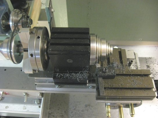 Fig
3.1.4.1: Finishing the Plate
Fig
3.1.4.1: Finishing the Plate
3.2 Drilling the Index Holes
I've seen quite a few references to improvised indexing techniques using circular saw blades but have never found a detailed how-to description. The following describes how I did it on the drill press but it should work equally well using a mill.
 Fig
3.2.1: Mounting Platform
Fig
3.2.1: Mounting Platform
From scrap plywood or particle board, make a platform with a base extending well beyond the headstock mounting and with risers to get the spindle 6" above the base. This provides a surface for clamping to the machine table and enough height to swing a 10" saw blade.
 Fig
3.2.2: Centering the Platform
Fig
3.2.2: Centering the Platform
Shift the platform so the drill chuck is centered radially over the pulley and index plate, then clamp it down to the machine table.
 Fig
3.2.3: Locating the Plate Axially
Fig
3.2.3: Locating the Plate Axially
Scribe lines on the index plate 5/64" in from each edge as center lines for each of the two rows of index holes. Shift the headstock on the mounting plate to center the drill chuck over one of the two scribed lines and tighten it in place.
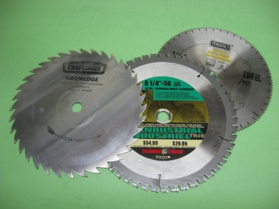 Fig 3.2.4:
The Saw Blades
Fig 3.2.4:
The Saw Blades
Select one of the saw blades you intend to use for indexing. I used a 36-tooth Craftsman and intended to use every third tooth of a 150-tooth Mibro; that is, until I discovered it really only had 140 teeth. Bummer! So I ended up using the borrowed 50-tooth blade shown.
 Fig
3.2.5: Mounting the Blade
Fig
3.2.5: Mounting the Blade
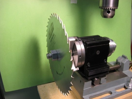
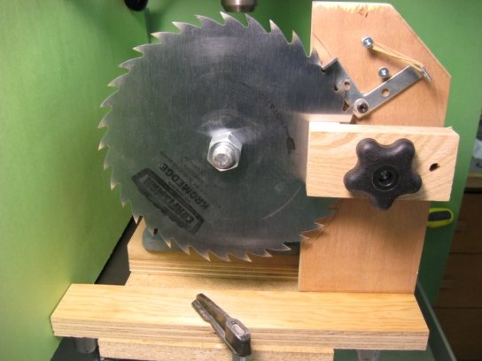 Fig 3.2.6:
The Saw Blade Detent and Lock
Fig 3.2.6:
The Saw Blade Detent and Lock
Mount the blade on a mandrel made with a couple of nuts on a short, headless 5/8" bolt held in the three-jaw chuck. Incremental rotation of the blade is controlled and locked with the simple device shown in Fig 3.2.6. The rubber band driven detent is very positive but the blade can still move
under torque. Such movement is prevented by a couple of turns on the hand knob to lock the blade by pinching it tightly between the pads of the disc brake. The assembly is most easily positioned by locking it onto the blade and then C-clamping it to the base.
 Fig
3.2.7: Dimensions of the Detent/Lock
Fig
3.2.7: Dimensions of the Detent/Lock
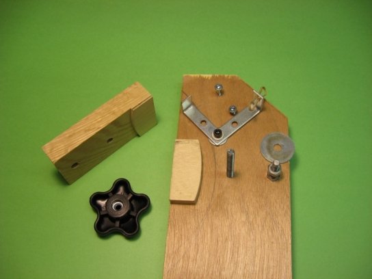 Fig
3.2.8: Detail of the Detent/Lock
Fig
3.2.8: Detail of the Detent/Lock
Here is a detailed look at the Detent/Lock Assembly.
The frame is made from scrap 3/4" plywood. The detent lever is bent from a 3" flat corner brace. It's pivot is a 10-32 socket head cap screw self-threaded into a 5/32" hole. The stop and rubber band anchor are #8 wood
screws. The clamp and spacer bolts are 1/4-20 self-threaded into 7/32" holes from the back. The disk pad thicknesses are 3/8" fixed, 1/8" movable, allowing for any set in the saw teeth. The 2 1/2" hand knob makes locking quick and convenient but an ordinary hex or wing nut would do just as well.
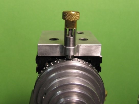
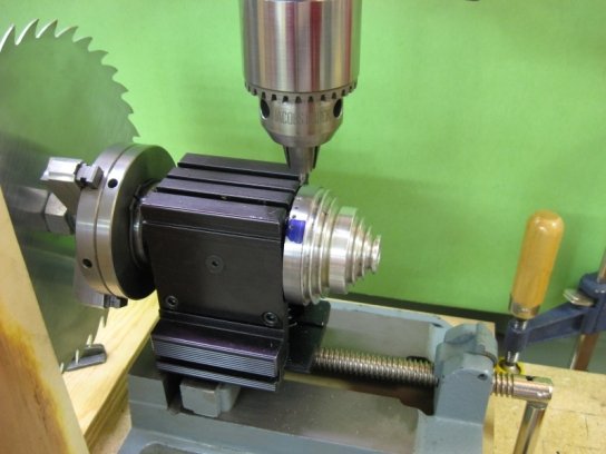 Figure 3.2.9: Drilling the First Row of
Holes
Figure 3.2.9: Drilling the First Row of
Holes
Now the first row of holes can be drilled. Select and lock each tooth of the saw blade to rotate the index plate to each successive hole location. Use a #1 center drill, but only deep enough to come about half way up the 60° countersink. This gives about a 3/32" target cone for the detent.
 Fig
3.2.10: Drilling the Second Row of Holes
Fig
3.2.10: Drilling the Second Row of Holes
Remove the detent mechanism and saw blade. Loosen the headstock, slide it along to line up with the line marked for the second row of holes and retighten. Install the next saw blade and reclamp the detent mechanism. Index and drill the second row of holes.
Here is the finished pulley and index plate.
 Fig
3.2.11: The finished Index Plate
Fig
3.2.11: The finished Index Plate
3.3 Detent Assembly
 Fig
3.3.1: Detent Dimensions
Fig
3.3.1: Detent Dimensions
All spring-loaded detents are pretty much the same and there's nothing special about this one.
Try to keep as little material as possible around the point where the detent enters the index plate hole. Otherwise it can be quite hard to see just which hole has been selected.
The #53 hole is to allow an .050 Allen key to be used for both tightening the knurled knob on the plunger and the whole assembly into the mounting plate.
The disengagement feature is not absolutely necessary and is hard to make without a mill or lathe milling attachment. In this case, the whole assembly would just be removed when not in use.
 Fig
3.3.2:The Detent Parts
Fig
3.3.2:The Detent Parts
 Fig
3.3.3: Detent Engaged
Fig
3.3.3: Detent Engaged
 Fig
3.3.4: Detent Disengaged
Fig
3.3.4: Detent Disengaged
© Copyright 2007 Keith Brooke [kbrooke@golden.net]. Queries and comments welcome. Please put the words 'Taig Indexing' in your e-mail subject to bypass my junk mail filter.
![]() This document produced
with
Free
HTML-Kit 292
This document produced
with
Free
HTML-Kit 292
![]()